June 23, 2026
How to Optimize Part Design for Metal Stamping
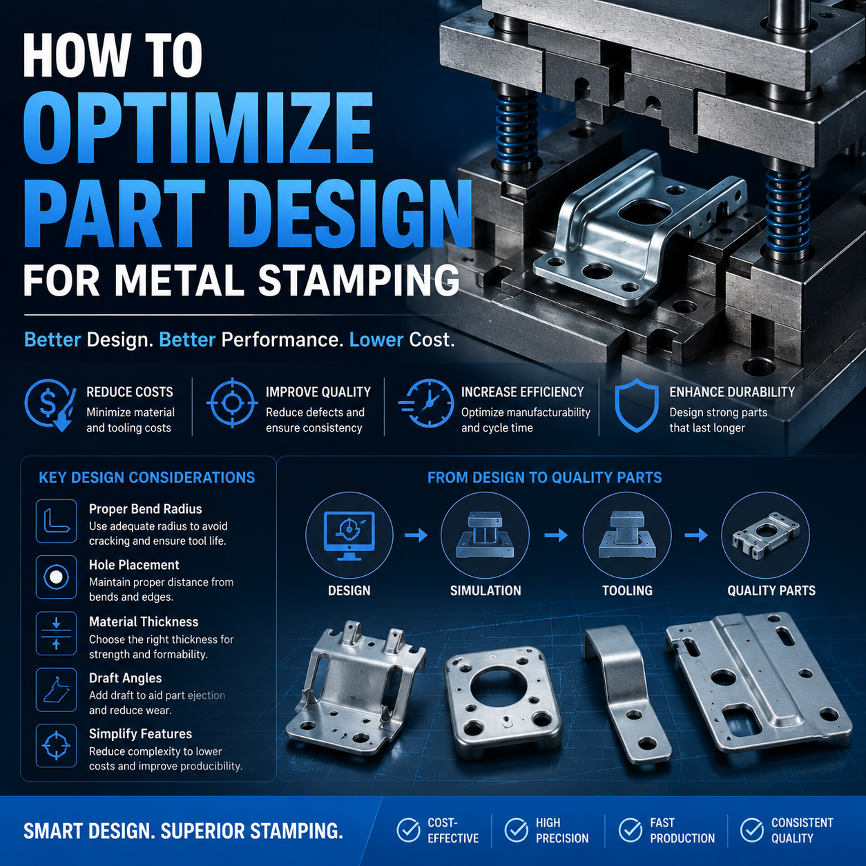
A practical guide for design engineers and procurement professionals to reduce cost, improve quality, and shorten lead times
Table of Contents
Introduction: Design Decisions Determine 70% of Cost
The Metal Stamping Process in Brief
Material Selection: The First and Biggest Decision
Wall Thickness and Taper: Avoiding Cracks and Tears
Bend Radii: The Most Common Mistake
Hole Placement and Spacing
Features That Drive Tooling Complexity
Tolerances: Tight Is Not Always Right
Design for Manufacturability Checklist
Case Study: A Bracket Redesigned to Save 40%
Conclusion
Introduction: Design Decisions Determine 70% of Cost
Here is something I have learned from working with both design teams and stamping shops. The decisions you make before you ever send a drawing to a supplier determine roughly 70% of the final part cost. Not the material price, not the stamping press time—the geometry itself.
A poorly designed part forces the toolmaker to add complexity, use exotic materials, or accept lower production speeds. A well-designed part runs smoothly, produces consistent quality, and keeps tool maintenance simple.
This guide covers the core principles of design for manufacturability (DFM) for metal stamping. I will walk you through material selection, bend radii, hole placement, tolerances, and the features that drive tooling cost. Whether you are a design engineer or a procurement professional reviewing supplier quotes, these principles will help you spot high-cost features before they go to production.
The Metal Stamping Process in Brief
Metal stamping is a cold-forming process that uses a die and a press to convert flat sheet metal into a desired shape. The sheet is fed into the press, and the die cuts, bends, or forms the material in a single stroke or a series of strokes.
Progressive stamping is the most common method for high-volume parts. A progressive die performs multiple operations—piercing, trimming, bending, embossing—at different stations as the strip moves through the press. Coining is used for precision features like embossed text or flatness corrections. Blanking cuts the part outline from the strip. Bending forms flanges and channels.
Understanding these basic operations helps you design parts that work with the process, not against it.
Material Selection: The First and Biggest Decision
Material choice affects every downstream parameter: die wear, minimum bend radius, springback, and final part cost.
Material | Relative Cost | Formability | Springback | Typical Applications |
Low-carbon steel (C1008/1010) | Low | Excellent | Low | Brackets, enclosures, general stamping |
Stainless steel (304, 430) | Medium-high | Moderate | Moderate | Food equipment, medical, automotive trim |
Aluminum (5052, 6061) | Medium | Good (5052) / Fair (6061-T6) | Moderate | Electronics, automotive lightweighting |
Copper / Brass | High | Good | Low | Electrical contacts, decorative parts |
High-strength steel (HSLA) | Medium | Poor | High | Structural, safety components |
For most stamped parts, low-carbon steel offers the best combination of formability, strength, and cost. Aluminum requires larger bend radii and is more prone to cracking. Stainless steel work-hardens quickly, which affects tool design.
Design rule: Specify the least expensive material that meets your functional requirements. Avoid exotic alloys unless absolutely necessary. A material change from stainless to cold-rolled steel can cut tool life fivefold and reduce per-part cost by 60% or more.
Wall Thickness and Taper: Avoiding Cracks and Tears
The thickness of the starting sheet—called the blank—is the foundation of your part design. Every bend, hole, and feature relates to this thickness.
Minimum hole diameter: For piercing, the hole diameter should be at least 1.2 to 1.5 times the material thickness. Smaller holes require special tooling and increase punch breakage risk.
Distance from hole to edge: Maintain a minimum distance of 1.5 to 2 times material thickness from the edge of a hole to the nearest part edge or bend. Too little material between a hole and an edge creates a weak bridge that can tear during stamping or in service.
Slot widths: Slots should be at least 1.5 times material thickness wide. Narrower slots require fragile punches and are prone to breakage.
Taper or draft: For deep drawn parts, adding a slight taper (1–2 degrees) to vertical walls allows the part to release from the die cleanly. Straight walls increase friction and can cause galling or part seizure.
A common mistake is designing features at the same thickness as the blank without considering the deformation that occurs during forming. A bend that is too tight will thin the material at the outside radius and may crack. A hole too close to a bend will elongate into an oval after forming.
Bend Radii: The Most Common Mistake
The inside bend radius is where most stamping designs go wrong. Designers often specify zero radius—a sharp, 90-degree corner—which is impossible to achieve without cracking.
The rule: The inside bend radius should be at least one times the material thickness for most steels. For aluminum, use 1.5 to 2 times thickness. Softer materials can accept tighter radii; harder materials require larger radii.
Material | Minimum inside bend radius (as multiple of thickness) |
Low-carbon steel | 0.5–1.0t |
Stainless steel (300 series) | 1.0–2.0t |
Aluminum (5052) | 1.0–1.5t |
Aluminum (6061-T6) | 2.0–3.0t |
High-strength steel | 2.0–4.0t |
Why this matters: A bend radius that is too tight causes cracking on the outside of the bend. It also increases springback, making the part harder to hold to tolerance. A generous radius reduces stress, allows the material to flow, and extends die life.
Bend direction relative to grain: Bending across the grain (perpendicular to the rolling direction) allows tighter radii. Bending with the grain parallel to the bend line increases cracking risk. Whenever possible, orient parts so that critical bends are across the grain. Your stamping supplier can advise on optimal blank orientation.
Hole Placement and Spacing
Holes near bends are a frequent source of deformation. When a bend is formed, the material on the outside stretches, and the material on the inside compresses. A hole too close to the bend will stretch into an oval or, in extreme cases, tear.
Distance from bend line: For holes up to 6 mm diameter, maintain a distance of at least 2.5 times material thickness plus the bend radius from the bend line. Larger holes need more clearance.
Distance between holes: Adjacent holes should be spaced at least 1.5 to 2 times material thickness apart. Closer spacing creates a weak web that can rupture.
Slot orientation relative to bend: If a slot must be placed near a bend, orient it parallel to the bend line whenever possible. A slot perpendicular to the bend will distort more severely.
For pierced features that must be very close to a bend, consider stamping the holes after bending. This requires a secondary operation and adds cost, but it may be cheaper than dealing with distorted holes or part rejection.
Features That Drive Tooling Complexity
Certain features significantly increase die complexity, tooling cost, and maintenance requirements.
Feature | Impact on Tooling | Recommendation |
Burrs on both sides of the sheet | Requires double shearing or secondary operation | Avoid unless functionally necessary |
Undercuts | Requires side-action cams, die complexity doubles | Eliminate or redesign |
Very tight tolerances (±0.05 mm) | Requires precision grinding, slower press speeds, more frequent maintenance | Specify only on critical mating features |
Sharp internal corners | Impossible with standard punches; requires wire EDM on die | Add fillets (0.5t minimum radius) |
Multiple bending directions | Requires complex die sequencing or multiple dies | Consolidate bends into one direction if possible |
Embossing or coining on curved surfaces | Difficult to control depth; may require secondary support | Use on flat surfaces only |
The principle: Every feature that requires a moving element in the die—a cam, a slide, a lift—adds thousands of dollars to tooling cost. Design parts to be stamped in as few directions as possible, ideally with all features accessible from the top or bottom of the strip.
Tolerances: Tight Is Not Always Right
Over-tolerancing is one of the most expensive design habits. A stamping shop can hold very tight tolerances—but every decimal place you add increases cost.
Standard stamping tolerances (without grinding or special processes):
Dimension type | Typical achievable tolerance (±mm) |
Blanked edges (flat pattern) | 0.10–0.25 mm |
Hole diameters | 0.05–0.10 mm |
Hole-to-hole position | 0.10–0.20 mm |
Bend angles | ±1 degree |
Formed feature heights | 0.15–0.30 mm |
Flatness (per 100 mm) | 0.20–0.40 mm |
If you specify a tolerance of ±0.05 mm on every dimension, expect to pay 3–5 times more for tooling and per-part pricing. The press must run slower. Tools require more frequent sharpening. Reject rates increase.
Design rule: Apply tight tolerances only to dimensions that truly matter—fit with other components, electrical clearance, or sealing surfaces. For all other dimensions, use standard commercial tolerances. The industry standard for general tolerances on stamped parts is often ISO 2768-m or equivalent.
One more note: Tolerances on formed features are larger than tolerances on flat features. Springback is difficult to predict exactly, so a bend angle tolerance of ±1 degree is standard. If you need tighter than that, plan for secondary calibration or coining operations.
Design for Manufacturability Checklist
Before finalizing your design, run through this checklist:
Material selected for formability, not just strength
Inside bend radius ≥ 1t for steel, ≥ 2t for aluminum
Hole diameter ≥ 1.5t
Hole-to-edge distance ≥ 1.5t
Hole-to-bend distance ≥ 2.5t + bend radius
Slot width ≥ 1.5t
Minimum corner radius (internal) ≥ 0.5t
Tolerances relaxed where not critical
Minimal use of side-action cams
Part can be fed through a progressive die without tangling
Grain direction considered for critical bends
Burrs specified on one side only (the side that will not be seen or affect fit)
If you can check all these boxes, your part is likely cost-effective to stamp. If not, prioritize the changes that will yield the biggest savings—usually bend radii and hole placement.
Case Study: A Bracket Redesigned to Save 40%
Let me share a real example.
The original design: A stamped steel bracket for an industrial control panel. The material was 2.0 mm thick 304 stainless steel. The design called for a 3 mm inside bend radius (1.5t—acceptable). Holes for mounting were placed 2 mm from the bend lines—well within the required clearance. Tolerances were ±0.1 mm on all hole positions and ±0.5 degrees on all bends.
The problem: The part was expensive. Tooling cost was quoted at $18,000. Per-part price at 10,000 pieces was $2.80.
The analysis: The stainless steel specification was driving high tool wear. The tight tolerance on bend angles (±0.5 deg) was forcing a slower press stroke and more frequent adjustments. The material could be changed to low-carbon steel with a zinc plating, which would meet the environmental requirements of the control panel application.
The redesign:
Changed material from 304 stainless to cold-rolled steel (CRS) with zinc plate
Relaxed bend angle tolerance from ±0.5 deg to ±1.0 deg
Increased hole-to-bend distance from 2 mm to 5 mm by moving a non-critical feature
Added a 0.5 mm radius to two sharp internal corners
The result: Tooling cost dropped to $11,000 (39% less). Per-part price dropped to $1.70 (40% less). The stamped parts functioned identically in the assembly. The zinc plating provided adequate corrosion protection for the indoor control panel application.
The lesson: Small changes in material selection and feature placement produced large savings. The design team spent an extra two hours on DFM review. That two hours saved $7,000 on tooling and $11,000 on the first production run.
Conclusion
Optimizing part design for metal stamping is not about accepting lower quality. It is about aligning your design with the capabilities of the stamping process—and avoiding the features that drive unnecessary cost.
The principles are straightforward: choose the most formable material that meets your needs. Use generous bend radii. Keep holes away from edges and bends. Relax tolerances wherever possible. Avoid undercuts and side actions. Design for a progressive die with minimal direction changes.
The financial impact is real. A DFM review that takes a few hours can reduce tooling cost by 30–50% and per-part cost by 20–40%. The best time to optimize is before the die is cut. The second-best time is before you approve the final drawing.
Work with your stamping supplier early. Most stamping shops have experienced tool designers who can review your part and suggest improvements at no cost. Use that resource. The few minutes you spend on a phone call can save thousands of dollars on your next production run.